Introduction.
Multiple hardware adapters have been built and tested. The proposed adapters currently only concern the level conversion for protocol emulation and not the analog/SPDIF conversion, so please check first that you have a SPDIF output on your PC or soundcard.Head unit connector.
The emulator is plugged into the CD changer connector, a 8-pin blue "mini-iso" connector at the back of the head unit.Where to get it ?
This connector can be found in multiple places but make sure that metallic contacts are provided (either pre-wired or to solder), because the connector is sometimes proposed as an empty shell. Car hi-fi stores are good sources but are sometimes expensive. eBay is another alternative and I personally bought one from Adaptershop (search on "blau").If you have an actual CD Changer and you're looking for a female connector to insert your adapter (with relay switching) between the CDC and HU, the cheapest way I could find is to dismantle a 1.3 m extender by Blaupunkt , ref 7 607 621 154.
Pinout
Here's a diagram of the head unit pinout. The connector we're interested in here is the blue one: C3.Warning : This pinout is for Philips/VDO/Dayton "Tuner List" and "Update List" head units only. Other models (i.e. Blaupunkt) are known to use the same physical connectors but with a different pin assignment.

(*) Central Communication Unit. This is the way the HU receives stalk control commands and sends information to the dash display.
(**) Auxiliary input only available on Update List models. The AUX input must be activated in the head unit's menu. C2 doesn't exist at all on Tuner List models
(***) Models before 2000 have an analog CD Changer audio input instead of SPDIF. In that case, the pinout is as follows: 18=Audio GND, 19=Audio Left and 20=Audio Right.
Sample circuits.
Note that multiple functions can be provided by following circuits. Not all circuits provide all functions, but you can probably easily combine different circuits if needed.These functions are :
- level adaptation in both directions : Mandatory.
- optical isolation between PC and head-unit : Optional or mandatory... depends on your PC and HU
- propagation of "remote out" signal from the HU to the PC (this wire is at 12V once HU is on and triggers "booting" of actual CD changers) : Optional.
- control of relays to switch back and forth between PC and actual CD Changer (if you have one) with the RTS signal : Optional (not done yet).
Original MAX3232-based version
For maximal RS232 compatibility, the first version used uses a MAX3232 to provide the correct levels to the PC.It has been built multiple times and works as long as the following condition is fulfilled :
Warning : this version of the adapter assumes HU ground and PC ground are shared, which is frequently not the case with inverter-powered PCs. Please check if it's the case for you. You might also run into ground loop noise.
Opto-isolated version
For optical isolation between PC and HU, here is a version using optocouplers. Please note that it relies on fixed levels provided on the RTS (+) and DTR (-) pins of the serial port. Latest versions of the software emulators provided here take care of this. HU_ON (aka HU_REMOTE) is transmitted to the PC, but note that latest software versions don't need it and determine if HU is on simply by checking they get reply to the requests.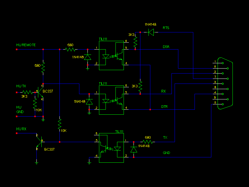
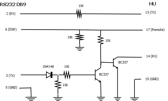
Simplest version
For maximum simplicity, here is a version without a single IC, only 2 transistors and a few passive components. It might or might not work depending on the thresholds of your PC's serial port.Warning : this version of the adapter assumes HU ground and PC ground are shared, which is frequently not the case with inverter-powered PCs. Please check if it's the case for you. You might also run into ground loop noise.
Full version
This version is inspired by the opto-coupled one above with slightly different parts. It also features a relay switching and is particularly suited if you have an actual CD changer in your car : if the carPC is off or the emulator is not running, the hardware emulator is disconnected and connection to the actual CDC is active, providing among other things a smooth transition when booting or shutting down.
 if
you feel it deserves it...
if
you feel it deserves it... |
This project is
hosted
by |
